In the previous blog, as part of our Gate Safety by Design series, we focused on the importance of end stops to prevent a sliding gate from over travelling. To reiterate: risk assessment is key to stop gates over travelling and design and construction of the gate is the first place to start. Eliminating the safety and construction risks from the gate design in the first instance will make for an inherently safer system that will also require less additional or safety features fitted on the gate when it is finally commissioned.
Since falling gates have represented such a high proportion of accidents in the last 10 years, we wanted to provide further detailed practical guidance to help installers adopt the best safety protocol to avoid any further incidents.
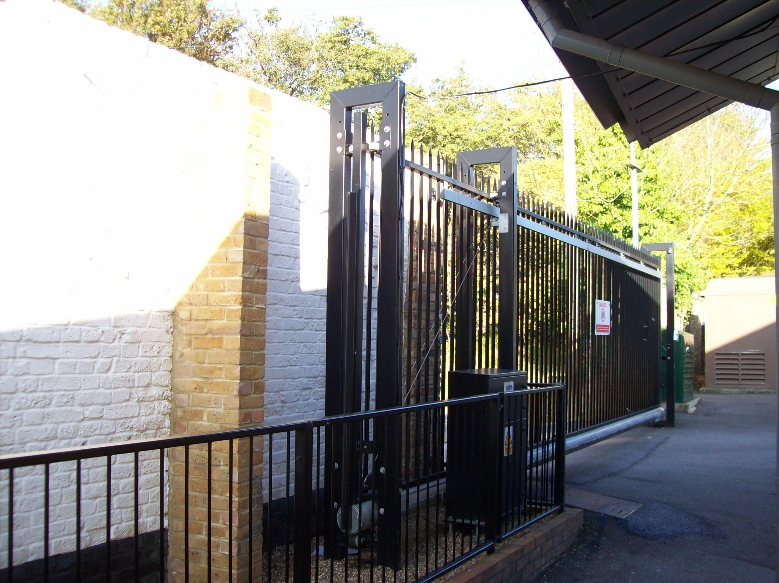
GATE SUPPORT POSTS
Ideally the gate should be supported between two goal post type supports or at least two hanging or suspension posts. This style of design will prevent the gate falling flat due to one component such as the roller breaking and causing a serious injury to anyone near the gate.
CORRECT FITTING OF ACTUATORS
Limit switches and their associated actuators or flags are probably the most common way that sliding gates are given their fully open and closed positions. These rely on the flags being positioned in the correct place, but importantly they must be secure to prevent them falling off because of vibration or physical contact.
We would recommend not only relying on the grub screw biting into the racking, but to fit an extra Tek screw or similar to deliver a much more solid and secure fixing that will guarantee that the flag cannot become detached from the gate. If the flag does detach, the limit switch will not be activated and the gate will over travel and will then be totally reliant on a strong physical stop.
PHYSICAL STOPS
It is essential that the physical stop in both opening and closing direction is capable of doing the job properly. If using the end plates on sliders that have internal rollers or wheels in the running tube, do not use screws to hold the end covers in place as these can easily be broken if the gate is running at full power. Instead, weld the end plates to ensure maximum strength and security. Make sure that channels that have support rollers running in them have strong end caps that are also welded in place.
Consider if there is any possibility that the gate rollers could over or underride the end stops, and then take the relevant steps to mitigate this – by fitting larger rollers. Ensure the roller fills the entire space within the channel and that there are sufficient end stops within the design to prevent the roller passing beyond its intended open or closed position. Ideally the roller should fill enough of the channel to prevent movement.
After determining the desired travel distance, fit the racking so it stops just after the limit switch would activate. This way if the limit switch fails, the gate would lose drive beyond this point and therefore would be rendered incapable of any over travel while the motor was running. ‘No rack, No drive’. Of course, this would have no effect if the gate was in manual release, so it is not a substitute for strong physical end stops.